Overview
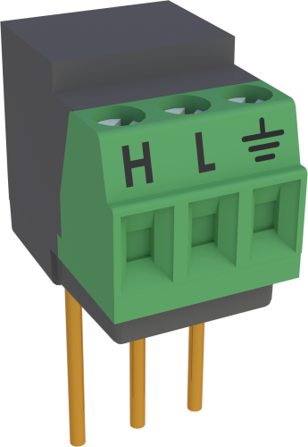
The 4WHB10K provides the completion resistor required for 4-wire half-bridge measurements. This module should be used with sensors that have a 10 kΩ resistance.
Read MoreBenefits and Features
- Makes accurate measurement of 10-kohm, 4-wire half bridges simple
- Easy to install or remove
- Connects directly into data logger input terminals
- Compatible with most Campbell Scientific data loggers
Images


3D/CAD Files:
Related Products
Technical Description
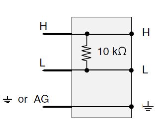
4WHB10K Schematic

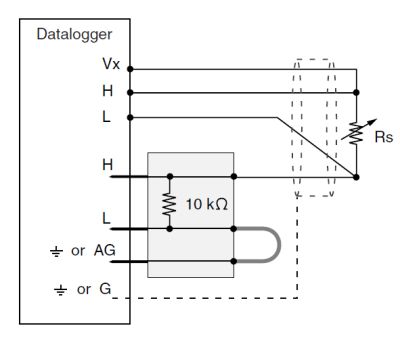
4WHB10K-to-Sensor Hookup

Compatibility
Please note: The following shows notable compatibility information. It is not a comprehensive list of all compatible products.
Dataloggers
| Product | Compatible | Note |
|---|---|---|
| 21X (retired) | ||
| CR10 (retired) | ||
| CR1000 (retired) | ||
| CR10X (retired) | ||
| CR200X (retired) | ||
| CR211X (retired) | ||
| CR216X (retired) | ||
| CR23X (retired) | ||
| CR300 (retired) | ||
| CR3000 (retired) | ||
| CR310 | ||
| CR350 | ||
| CR500 (retired) | ||
| CR5000 (retired) | ||
| CR510 (retired) | ||
| CR6 | ||
| CR800 (retired) | ||
| CR800 (retired) | ||
| CR800 (retired) | ||
| CR850 (retired) | ||
| CR850 (retired) |
Miscellaneous
| Product | Compatible | Note |
|---|---|---|
| CR9050 (retired) |
Additional Compatibility Information
Data Logger Considerations
The 4WHB10K uses two sequential differential analog inputs; the first differential channel must have an adjacent analog ground channel to accept the "ground prong" of the 4WHB10K. Not all data logger terminal strips have this sequence on all channels, so please check your data logger's wiring panel to confirm channel assignments, especially if you plan to use multiple Terminal Input Modules.
Newer CR10X Wiring Panels and the CR10XTCR Thermocouple Cover are deep enough to cover the data logger input channels with a Terminal Input Module attached; older CR10TCRs are not deep enough.
Programming
The 4WHB10K is measured either with CRBasic's BrHalf4W Instruction or Edlog's Instruction 9 (Full-Bridge with Excitation Compensation).
Specifications
| Used With | 4-wire half bridge measurements with a 10 kΩ resistance |
| Resistance | 10 kΩ (bulk metal foil) |
| Tolerance | ±0.01% (@ 25°C) |
| Maximum Temperature Coefficient | ±0.8 ppm/°C |
| Power Rating | 0.25 W (@ 70°C) |
| Dimensions | 1.5 x 1.5 x 2.7 cm (0.6 x 0.6 x 1.0 in.) for body with prongs |
| Weight | 6 g (0.2 oz) |
Related Documents
Product Brochures
Related FAQs
Number of FAQs related to 4WHB10K: 1
-
For more information, refer to the “PRT in 4 Wire Half Bridge” section in the 4WPB100, 4WPB1K PRT Bridge Terminal Input Modules Instruction Manual. Figure 2-1 in the manual provides a circuit schematic.


