Ideal for small applications


View the QuickStart Guide
Overview
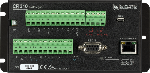
The CR310 is a multi-purpose, compact, low-cost measurement and control data logger that includes an integrated 10/100 Ethernet port and removable terminal connectors. This entry-level data logger, with its rich instruction set, can measure most hydrological, meteorological, environmental, and industrial sensors. It will concentrate data, making it available over varied networks and deliver it using your preferred protocol. The CR310 also performs automated on-site or remote decision making for control and M2M communications. The CR310 is ideal for small applications requiring long-term, remote monitoring and control.
The primary differences between the CR300 and CR310 are that the CR310 offers removable connectors and a 10/100 Ethernet connection.
The CR310 has multiple radio options that are suitable for different regions:
- CR310-RF407: US and Canada
- CR310-RF412: Australia and New Zealand
- CR310-RF422: Europe
- CR310-RF427: Brazil
Note: Campbell Scientific does not recommend the CR310 for use as a PakBus router in networks with more than 50 devices. Large arrays or string variables may also reach memory limits. For such applications, a CR1000X Measurement and Control Datalogger is recommended.
Read MoreBenefits and Features
- Set up easily with PC software and USB connectivity
- Measure with confidence analog and digital sensors
- Internet ready–email, FTP, HTTP/web, TCP
- Trust in the Campbell Scientific quality, including integral surge and ESD protection
- Save money and space using the integrated Ethernet port
- Network wirelessly to another node or Internet gateway with integrated radio option
- CR310-WIFI ideal for short-range, wireless IP communication
- Wiring made easy through removable terminal block
- Communicate from anywhere when using cellular or satellite peripheral
- Charge batteries using the integrated 12 V battery solar charge regulator
- Measure smart sensors using RS-232 or SDI-12
- Connect with PakBus, Modbus, DNP3, GOES, and other standard communication protocols
- Analyze and control with programmability and multiple general purpose I/O
- Notify with event-driven communications and physical outputs
Technical Description
Terminal Descriptions
- One switched 12 V terminal (SW12V) for powering sensors or communication devices, 1100 mA @ 20°C
- Two sensor excitation or continuous 0.15 to 5 V terminals (VX1, VX2) for sensor excitation or output control
- Six multipurpose analogue input terminals (SE1 - SE6)
- Analogue functions (SE1 - SE6)
- Analogue inputs: 6 single-ended or 3 differential inputs with -100 to +2500 mV and ±34 mV ranges 24 bit ADC
- 4 to 20 mA or 0 to 20 mA inputs (SE1, SE2 only)
- Digital I/O functions (SE1 - SE4) consist of 3.3 V logic levels for:
- High frequency counter (35 kHz)
- Pulse width modulation
- Interrupts and timer input
- Period average (200 kHz, amplitude dependent)
- Analogue functions (SE1 - SE6)
- Two Pulse Counting Terminals (P_SW, P_LL)
- P_SW
- Switch closure (150 Hz)
- High frequency counter (35 kHz)
- P_LL
- Low level ac (20 kHz)
- High frequency counter (20 kHz)
- P_SW
- Two Control Terminals (C1, C2): C terminals are software configurable for digital functions
- Digital I/O functions consist of 5 V output and 3.3 V input logic levels for:
- SDI-12
- High frequency counter (3 kHz)
- Switch closure (150 Hz)
- General status/control
- Voltage source 5 V: 10 mA @ 3.5 V
- Interrupts
- Serial asynchronous communication Tx/Rx pair
- Digital I/O functions consist of 5 V output and 3.3 V input logic levels for:
Videos & Tutorials
Compatibility
Please note: The following shows notable compatibility information. It is not a comprehensive list of all compatible products.
Sensors
| Product | Compatible | Note |
|---|---|---|
| PC400 | Version 4.4 or higher |
Software
| Product | Compatible | Note |
|---|---|---|
| LoggerNet | Version 4.4 or higher | |
| LoggerNet Mobile Connect | Version 1.1 or higher | |
| RTDAQ |
Miscellaneous
| Product | Compatible | Note |
|---|---|---|
| DevConfig | Version 2.12 or higher | |
| LoggerLink | Version 1.5 or higher | |
| PC200 (retired) | Version 4.4 or higher | |
| Short Cut | Version 3.2 or higher |
Additional Compatibility Information
Measurement & Control Peripherals
The CR310 is typically not used with measurement and control peripherals because of its limited number of control ports. It is also compatible with low on current and voltage solid-state relays.
The CR310 is not compatible with SDM or CDM devices.
Sensors
With several channel types, the CR310 is compatible with nearly every available sensor. This includes analog output voltage (0 to 2.5 V) and current (0 to 20 mA or 4 to 20 mA) sensors, thermistors, and RTDs to name a few. It is also compatible with pulse or frequency output sensors such as anemometers, rain gauges, and flow meters. CR310 dataloggers are not capable of applying reverse excitation, and they cannot be used with some conductivity or soil matric potential sensors.
SDI-12, Modbus, and other serial sensors are supported with the RS-232 port and C1 and C2 as a Tx/Rx pair. The CR310 does not directly support RS-485 sensors.
Communications
The CR310 can communicate with a PC via its USB port. Compatible telemetry devices include our RS-485 converters, digital cellular gateways, RF telemetry, and satellite transmitters. Data can be viewed on an iOS device, an Android device, or CD295 DataView II Display. To use an iOS or Android device, go to the Apple Store or Google Play and download our free LoggerLink Mobile Apps.
| Data Logger Option | Communications Type | Integrated Communications Are Compatible with |
|
CR310-WIFI |
2.4 GHz, 20 MHz bandwidth |
Most other Wi-FI devices, such as the CR300-WIFI, CR6-WIFI, NL240 |
|
CR310-RF407 |
902 to 928 MHz Frequency Hopping Spread Spectrum |
|
|
CR310-RF412 |
915 to 928 MHz Frequency Hopping Spread Spectrum |
|
|
CR310-RF422 |
868 MHz SRD860 LBT+AFA |
|
|
CR310-CELL |
2G Frequency Bands 850, 900, 1800, 1900 |
GSM/GPRS/EDGE (2G) |
Software
The CR300 series is compatible with CRBasic (version 3.6 or higher).
Power
The CR310 uses an external power source and has a built-in charger/regulator. Intelligent power sourcing autoselects the highest voltage from three input sources (Chg, Bat, or USB) to operate in one of the following four modes:
- UPS (recommended) - A 16 to 32 Vdc source, solar panel (SP10, SP20), or power converter (29796) is used to charge a 12 Vdc battery, such as our BP7 or BP12.
- 12 Vdc battery or other reliable 12 Vdc source
- Chg only - DC power supply (16 to 32 Vdc)
- USB - Powered over 5 Vdc USB port for setup, programming, and testing (will not charge battery or boost USB power to provide 12 Vdc to the switched battery terminal SW12)
Enclosures
An ENC10/12 or ENC12/14 enclosure is adequate for most CR310-based systems.
Specifications
| -NOTE- | Additional specifications are listed in the CR300-Series Specifications Sheet. |
| Operating Temperature Range |
|
| Maximum Scan Rate | 10 Hz |
| Case Material | Powder-coated aluminum |
| Analog Inputs | 6 single-ended or 3 differential (individually configured) |
| Pulse Counters | 8 (P_SW, P_LL, C1, C2, and SE1 to SE4) |
| Voltage Excitation Terminals | 2 (VX1, VX2) |
| Communications Ports |
|
| Switched 12 Volt | 1 terminal |
| Digital I/O | 7 terminals (C1, C2, P_SW, and SE1 to SE4) configurable for digital input and output. Includes status high/low, pulse width modulation, external interrupt, and communication functions. Exception: The SE4 terminal doesn't do external interrupt. |
| Input Limits | -100 to +2500 mV |
| Analog Voltage Accuracy |
|
| ADC | 24-bit |
| Charge Terminal Characteristics (CHG+ and CHG-) |
|
| Battery Terminal Characteristics (BAT+ and BAT-) |
|
| Internal Lithium Battery |
|
| Real-Time Clock Accuracy | ±1 min. per month |
| Internet Protocols | Ethernet, PPP, RNDIS, ICMP/Ping, Auto-IP(APIPA), IPv4, IPv6, UDP, TCP, TLS (v1.2), DNS, DHCP, SLAAC, NTP, Telnet, HTTP(S), FTP(S), SMTP/TLS, POP3/TLS |
| Communication Protocols | PakBus, Modbus, DNP3, SDI-12, TCP, UDP, and others |
| CPU Drive/Programs | 80 MB serial flash |
| Data Storage | 30 MB serial flash |
| Idle Current Drain, Average | 10 mA (@ 12 Vdc with Ethernet link idle) |
| Active Current Drain, Average | 56 mA (@ 12 Vdc with Ethernet link active, processor always on) |
| Dimensions | 16.26 x 7.62 x 5.68 cm (6.4 x 3.0 x 2.2 in.) |
| Weight | 288 to 306 g (0.64 to 0.68 lb) depending on communication option selected |
CR310-RF407 Option |
|
| Radio Type | Frequency Hopping Spread Spectrum (FHSS) |
| Output Power | 5 to 250 mW (user-selectable) |
| Frequency | 902 to 928 MHz (US, Canada) |
| RF Data Rate | 200 kbps |
| Receive Sensitivity | -101 dBm |
| Antenna Connector | RPSMA (external antenna required; see www.campbellsci.com/order/rf407 for Campbell Scientific antennas) |
| Idle Current Drain, Average | 12 mA (@ 12 Vdc) |
| Active Current Drain, Average | < 80 mA (@ 12 Vdc) |
CR310-RF412 Option |
|
| Radio Type | Frequency Hopping Spread Spectrum (FHSS) |
| Output Power | 5 to 250 mW (user-selectable) |
| Frequency | 915 to 928 MHz (Australia, New Zealand) |
| RF Data Rate | 200 kbps |
| Receive Sensitivity | -101 dBm |
| Antenna Connector | RPSMA (external antenna required; see www.campbellsci.com/order/rf412 for Campbell Scientific antennas) |
| Idle Current Drain, Average | 12 mA (@ 12 Vdc) |
| Active Current Drain, Average | < 80 mA (@ 12 Vdc) |
CR310-RF422 Option |
|
| Radio Type | 868 MHz SRD 860 with Listen Before Talk (LBT) and Automatic Frequency Agility (AFA) |
| Output Power | 2 to 25 mW (user-selectable) |
| Frequency | 863 to 870 MHz (European Union) |
| RF Data Rate | 10 kbps |
| Receive Sensitivity | -106 dBm |
| Antenna Connector | (External antenna required; see www.campbellsci.com/order/rf422 for Campbell Scientific antennas.) |
| Idle Current Drain, Average | 9.5 mA |
| Active Current Drain, Average | 20 mA |
CR310-RF427 Option |
|
| Radio Type | Frequency Hopping Spread Spectrum (FHSS) |
| Output Power | 5 to 250 mW (user-selectable) |
| Frequency | 902 to 907.5 MHz/915 to 928 MHz (Brazil) |
| RF Data Rate | 200 kbps |
| Receive Sensitivity | -101 dBm |
| Antenna Connector | RPSMA (External antenna required.) |
| Idle Current Drain, Average | 12 mA (@ 12 Vdc) |
| Active Current Drain, Average | < 80 mA (@ 12 Vdc) |
CR310-WIFI Option |
|
| Operational Modes | Client or Access Point |
| Operating Frequency | 2.4 GHz, 20 MHz bandwidth |
| Antenna Connector | Reverse Polarity SMA (RPSMA) |
| Antenna | pn 16005 unity gain (0 dBd), 1/2 wave whip, omnidirectional with articulating knuckle joint for vertical or horizontal orientation |
| Transmit Power | 7 to 18 dBm (5 to 63 mW) |
CR310-CELL205 Option |
|
| -NOTE- | The CR310-CELL205 option is not compatible with a Verizon cellular network. |
| Cell Technologies |
|
| 3G Frequency Bands | 850, 1700/2100 (AWS), and 1900 |
| 4G Frequency Bands | 700, 850, 1700/2100 (AWS-1), 1900 |
| Antenna Connector | SMA (External antenna required; see www.campbellsci.com/order/cr310 for Campbell Scientific antennas.) |
| SIM Interface |
3FF (6 position/contacts) Supports SIMs that require 1.8 or 3 V. |
CR310-CELL210 Option |
|
| -NOTE- | The CR310-CELL210 option is only compatible with a Verizon cellular network. CR310-CELL205 Option No |
| Cell Technologies | 4G (LTE CAT-1) |
| 4G Frequency Bands | 700, 850, 1700, 1900, 2100 |
| Antenna Connector | SMA (External antenna required; see www.campbellsci.com/order/cr310 for Campbell Scientific antennas.) |
| SIM Interface |
3FF (6 position/contacts) Supports SIMs that require 1.8 or 3 V. |
CR310-CELL215 Option |
|
| -NOTE- | The CR310-CELL215 option is intended for use in EMEA countries. |
| Cell Technologies |
|
| 2G Frequency Bands | 900 and 1800 MHz |
| 3G Frequency Bands | 850, 900, and 2100 MHz |
| 4G Frequency Bands | 800, 850, 900, 1800, 2100, and 2600 MHz |
| Antenna Connector | SMA (External antenna required; see www.campbellsci.com/order/cr310 for Campbell Scientific antennas.) |
| SIM Interface |
3FF (6 position/contacts) Supports SIMs that require 1.8 or 3 V. |
CR310-CELL220 Option |
|
| -NOTE- | The CR310-CELL220 option is intended for use in Australia and New Zealand. |
| Cell Technologies |
|
| 3G Frequency Bands |
|
| 4G Frequency Bands |
|
| Antenna Connector | SMA (External antenna required; see www.campbellsci.com/order/cr310 for Campbell Scientific antennas.) |
| SIM Interface |
3FF (6 position/contacts) Supports SIMs that require 1.8 or 3 V. |
CR310-CELL225 Option |
|
| -NOTE- | The CR310-CELL225 option is intended for use in Japan. |
| Cell Technologies | 4G (LTE CAT-1) |
| 4G Frequency Bands | 800 (lower), 800 (upper), 850+, 900, 1800, and 2100 MHz |
| Antenna Connector | SMA (External antenna required; see www.campbellsci.com/order/cr310 for Campbell Scientific antennas.) |
| SIM Interface |
3FF (6 position/contacts) Supports SIMs that require 1.8 or 3 V. |
Related Documents
Product Brochures
Manuals
Technical Papers
Compliance
Downloads
CR300 Series OS v.11.02 (5.19 MB) 06-02-2025
This download is for the CR300 series of dataloggers including all CR300 and CR310 models. Execution of this download places the Operating System file(.obj) on your computer. It also updates the CRBasic Editor compiler and support files.
Why Update? This OS adds Campbell Cloud compatibility enhancements and resolves bugs found in the previous OS. See the revision history for a complete list. With this OS update, it is recommended that you also update the Device Configuration Utility to the most recent version so that new datalogger features are available in the utility.
Note/Warning: Campbell Scientific always recommends updating operating systems on site if possible. When remote updates are required, it is recommended that you implement the necessary precautions to handle unexpected OS upload complications. All datalogger settings should be retained when updated remotely. If you choose to roll back to a previous operating system, the datalogger settings will be reset to default.
Watch the Video Tutorial: Sending an OS to a Local Datalogger.
CR300 Series Wifi OS Update v.1.7.12 (1.97 MB) 13-05-2022
Manufacturer chipset maintenance update.
CR300 QuickStart Program (569 KB) 15-03-2016
The CRBasic program referenced in the CR300 QuickStart videos and manual.
Data Logger Wiring Excel Template (1 KB) 26-03-2024
This is a data logger wiring diagram spreadsheet template that accompanies the Wiring Diagram Video. The spreadsheet includes templates for CR6, CR1000X, CR300, CR310, and CR350 data loggers. The file is an Excel template and works best with Microsoft Excel.
Related FAQs
Number of FAQs related to CR310: 1
Articles and Press Releases
Press Releases
Case Studies
In 2019, Campbell Scientific embarked on a significant project with the Malawi Department of Climate......read more
Solar energy is the most abundant clean energy source available on earth, but the intermittent......read more
The Port of Townsville Limited (POTL) are undertaking the Channel Upgrade Project (CU Project). The......read more
The Panama Canal was using an outdated water-level system until the Panama Canal Authorities (ACP)......read more


