This product is no longer available. Some accessories, replacement parts, or services may still be available.

| Services Available | |
|---|---|
| Repair | No |
| Calibration | No |
| Free Support | No |
Overview
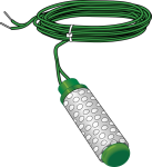
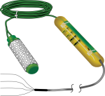
The 227, manufactured by Delmhorst, is a cylindrical gypsum block that estimates soil water potential from -10 to -1000 kPa. It connects directly to a datalogger.
Read MoreBenefits and Features
- Compatible with most Campbell Scientific data loggers
- Contains blocking capacitors in its cable that minimize galvanic degradation and measurement errors due to ground loops
- Measures wide range of matric potential
- Buffers salts in soil
- No maintenance required
Images

Technical Description
The 227 determines soil water potential by measuring electrical resistance. When the 227 is wet, electrical resistance is low. As the 227 dries, resistance increases.
The 227 cylindrical block is composed of gypsum cast around two concentric electrodes, which confine current flow to the interior of the block, greatly reducing potential ground loops. Gypsum located between the outer electrode and the soil creates a buffer against salts that may affect the electrical conductivity.
Campbell Scientific recommends removing the 227 during winter.
Compatibility
Please note: The following shows notable compatibility information. It is not a comprehensive list of all compatible products.
Dataloggers
| Product | Compatible | Note |
|---|---|---|
| 21X (retired) | ||
| CR10 (retired) | ||
| CR1000 (retired) | ||
| CR10X (retired) | ||
| CR200X (retired) | ||
| CR211X (retired) | ||
| CR216X (retired) | ||
| CR23X (retired) | ||
| CR3000 (retired) | ||
| CR500 (retired) | ||
| CR5000 (retired) | ||
| CR510 (retired) | ||
| CR800 (retired) | ||
| CR800 (retired) | ||
| CR800 (retired) | ||
| CR800 (retired) | ||
| CR850 (retired) | ||
| CR850 (retired) | ||
| CR850 (retired) | ||
| CR850 (retired) | ||
| CR9000 (retired) | ||
| CR9000X (retired) |
Additional Compatibility Information
Data Logger Considerations
Two single-ended channels and one excitation channel per probe are required.
Specifications
| Material | Gypsum |
| Measurement Range | -10 to -1000 kPa |
| Calibration | Individual calibrations are required for accurate measurements. Refer to the sensor manual for more information. |
| Operating Temperature | Soil temperatures above freezing |
| Life Expectancy | Two freeze-thaw cycles |
| Electrode Description | Concentric cylinders |
| Center Electrode | Excitation |
| Outer Electrode | Ground |
| Cylinder Diameter | ~2.25 cm (0.88 in.) |
| Cylinder Length | ~2.86 cm (1.25 in.) |
| Weight | 180 g (0.4 lb) |
Related Documents
Related FAQs
Number of FAQs related to 227-L: 2
-
Most Campbell Scientific sensors are available as an –L, which indicates a user-specified cable length. If a sensor is listed as an –LX model (where “X” is some other character), that sensor’s cable has a user-specified length, but it terminates with a specific connector for a unique system:
- An –LC model has a user-specified cable length for connection to an ET107, CS110, or retired Metdata1.
- An –LQ model has a user-specified cable length for connection to a RAWS-P weather station.
If a sensor does not have an –L or other –LX designation after the main model number, the sensor has a set cable length. The cable length is listed at the end of the Description field on the product’s Ordering tab. For example, the 034B-ET model has a description of “Met One Wind Set for ET Station, 67 inch Cable.” Products with a set cable length terminate, as a default, with pigtails.
If a cable terminates with a special connector for a unique system, the end of the model number designates which system. For example, the 034B-ET model designates the sensor as a 034B for an ET107 system.
- –ET models terminate with the connector for an ET107 weather station.
- –ETM models terminate with the connector for an ET107 weather station, but they also include a special system mounting, which is often convenient when purchasing a replacement part.
- –QD models terminate with the connector for a RAWS-F Quick Deployment Station.
- –PW models terminate with the connector for a PWENC or pre-wired system.
-
Many Campbell Scientific sensors are available with different cable termination options. These options include the following:
- The –PT (–PT w/Tinned Wires) option is the default option and does not display on the product line as the other options do. The cable terminates in pigtails that connect directly to a datalogger.
- In the –C (–C w/ET/CS110 Connector) option, the cable terminates in a connector that attaches to a CS110 Electric Field Meter or an ET-series weather station.
- In the –CWS (–CWS w/CWS900 Connector) option, the cable terminates in a connector that attaches to a CWS900-series interface. Connection to a CWS900-series interface allows the sensor to be used in a wireless sensor network.
- In the –PW (–PW w/Pre-Wire Connector) option, the cable terminates in a connector that attaches to a prewired enclosure.
- In the –RQ (–RQ w/RAWS Connector) option, the cable terminates in a connector that attaches to a RAWS-P Permanent Remote Automated Weather Station.
Note: The availability of cable termination options varies by sensor. For example, sensors may have none, two, or several options to choose from. If a desired option is not listed for a specific sensor, contact an application engineer at Campbell Scientific for assistance.


