Competitive price


Overview
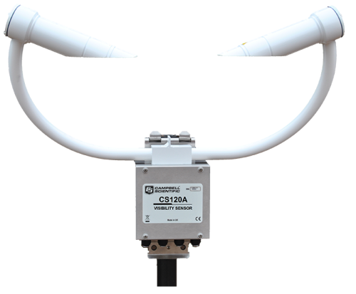
The CS120A uses tried-and-tested, infrared forward-scatter technology, and it uses the proven 42° scatter angle to report meteorological observable range (MOR) for fog and snow in the range of 5 to 75,000 m (16.4 to 246,063 ft). It combines a high specification with a very competitive price. The CS120A is ideal for stand-alone applications or in combination with automatic weather stations in road, aviation, solar-energy, and wind-energy environments.
For aviation applications, users can be assured that the CS120A complies with CAA and ICAO guidance and meets or exceeds all recommendations and specifications. (This includes CAP437, CAP670, and CAP746.)
The CS120A is certified by Deutscher Wetterdienst as suitable for use to control wind turbine obstruction light systems as specified by 506/04, General Administrative Rules for the Identification of Aircraft Obstructions.
Read MoreBenefits and Features
- High performance sensor at a competitive price
- Sensor design minimizes airflow disruption at measurement volume
- Incorporates automatic dew and hood heaters for all-weather operation
- Simple field calibration using optional calibration kit
- Low power—suitable for remote application
- Automatic status check for faults or window contamination
Images


Related Products
Technical Description
Compared to many such sensors, the CS120A design means that visibility is being measured in a relatively clean space because the position of the heads and body minimize disturbance of the airflow at the measurement volume.
The CS120A uses continuous high-speed sampling, which improves the accuracy of the measurements taken during mixed weather such as rain and hail, while providing reliable readings during more stable events such as fog and mist. High-speed sampling also allows the sensor to better respond to suddenly changing conditions.
The CS120A has several design features that keep its optics clean. Downward-facing optics minimize dirt and snow buildup. Low-powered heaters prevent the formation of dew, and a higher-powered heater prevents the formation of ice.
The sensor is very power efficient, drawing just 3 W during normal operation including the dew heaters; power can be reduced further by reducing the sample rate and manual control of the heaters.
Two configurable alarm outputs are provided and, via relays, these can drive external warning systems such as lights and foghorns. They can also be used to switch the intensity of wind turbine warning lights depending upon current visibility levels.
Compatibility
Please note: The following shows notable compatibility information. It is not a comprehensive list of all compatible products.
Specifications
| Signal Type/Output | RS-232, RS-485 |
| Measurement Description | Meteorological Observable Range (MOR) |
| Maximum Reported Visibility | 100 km (62.1 mi) |
| Minimum Reported Visibility | 5 m (16.4 ft) |
| Accuracy |
|
| Resolution | 1 m (3.3 ft) |
| Mounting | Stainless-steel V-bolt bracket that attaches to a pole with a 32 to 52.5 mm (1.25 to 2 in.) outer diameter |
| Electronics Supply Voltage | 7 to 30 Vdc |
| Total Unit Power | < 3 W while sampling continuously (including dew heaters) |
| Standards | Frangible masts are available to customer requirements to meet ICAO recommendations (typically placing the sample volume at 2.5 m [8.2 ft]). |
| Sensor Dimensions | 540 x 640 x 246 mm (21.26 x 25.2 x 9.7 in.) including mount |
| Sensor Weight | ~3 kg (6.6 lb) depending on mounting system |
Optical/Pulse |
|
| LED Center Wavelength | 850 nm |
| LED Spectral Bandwidth | ±35 nm |
| Light Pulse Rate | 1 kHz |
Environmental |
|
| Operating Temperature Range | -25° to +60°C (standard) |
| Extended Operating Temperature Range | -40° to +70°C (This extended version is available as a special. Contact Campbell Scientific for more information.) |
| Operating Humidity Range | 0 to 100% |
| Sensor Sealing | Rated to IP66 |
| Wind Speed | Up to 60 m s-1 |
| Sensor Heater Threshold |
|
DSP & Dew Heaters |
|
| Power | 2 x 0.6 W (total of 1.4 W) for dew heater |
| Typical Current Consumption @ 12 Vdc |
|
Hood Heater |
|
| Supply Voltage | 24 V dc or ac |
| Power | 2 x 30 W (total of 60 W) |
Interface |
|
| Serial Interface | RS-232 or RS-485, 8 bit data bytes, 1 stop bit |
| Serial Data Rates | 1200 to 115,200 bps (38,400 bps default rate) |
Related Documents
Product Brochures
Downloads
CR1000X CS120A example programs v.1 (2 KB) 18-03-2020
CR1000X programs that use the MSSET and MSGET commands.
CS125 and CS120A OS v.17 (555 KB) 08-06-2023
Campbell Scientific has introduced a new operating system, OS 17, for the CS120A visibility sensor and CS125 present weather sensor. It is backwards compatible and is easily installed on all CS120A and CS125 sensors (but not older CS120 sensors). OS 17 is available free of charge and can be downloaded here or supplied by email on request.
Upgrade to OS 17 is recommended.
Campbell Viewpoint v.2.1.0.2 (86 MB) 09-10-2019
Campbell Viewpoint is viewing software designed to accompany the Campbell Scientific optical sensor range, including the CS135 ceilometer, SkyVue PRO, SkyVue 8, SkyVue 8M, CS120A visibility and CS125 present weather sensors. It is free to download (or via email on request) and use for 100 hours, after which you will need to purchase a key to continue using it.
Version 2.1.0.2
Viewpoint version 2.1.0.2 has introduced our new ceilometer sensors to the list of instruments that can be monitored. This includes the SkyVue PRO, SkyVue 8 and SkyVue 8M.
Previous sensors are still available.
Version 2.1.0.2 also includes some minor bug fixes and improvements to the help menu.
Related FAQs
Number of FAQs related to CS120A: 2
-
Most Campbell Scientific sensors are available as an –L, which indicates a user-specified cable length. If a sensor is listed as an –LX model (where “X” is some other character), that sensor’s cable has a user-specified length, but it terminates with a specific connector for a unique system:
- An –LC model has a user-specified cable length for connection to an ET107, CS110, or retired Metdata1.
- An –LQ model has a user-specified cable length for connection to a RAWS-P weather station.
If a sensor does not have an –L or other –LX designation after the main model number, the sensor has a set cable length. The cable length is listed at the end of the Description field on the product’s Ordering tab. For example, the 034B-ET model has a description of “Met One Wind Set for ET Station, 67 inch Cable.” Products with a set cable length terminate, as a default, with pigtails.
If a cable terminates with a special connector for a unique system, the end of the model number designates which system. For example, the 034B-ET model designates the sensor as a 034B for an ET107 system.
- –ET models terminate with the connector for an ET107 weather station.
- –ETM models terminate with the connector for an ET107 weather station, but they also include a special system mounting, which is often convenient when purchasing a replacement part.
- –QD models terminate with the connector for a RAWS-F Quick Deployment Station.
- –PW models terminate with the connector for a PWENC or pre-wired system.
-
Many Campbell Scientific sensors are available with different cable termination options. These options include the following:
- The –PT (–PT w/Tinned Wires) option is the default option and does not display on the product line as the other options do. The cable terminates in pigtails that connect directly to a datalogger.
- In the –C (–C w/ET/CS110 Connector) option, the cable terminates in a connector that attaches to a CS110 Electric Field Meter or an ET-series weather station.
- In the –CWS (–CWS w/CWS900 Connector) option, the cable terminates in a connector that attaches to a CWS900-series interface. Connection to a CWS900-series interface allows the sensor to be used in a wireless sensor network.
- In the –PW (–PW w/Pre-Wire Connector) option, the cable terminates in a connector that attaches to a prewired enclosure.
- In the –RQ (–RQ w/RAWS Connector) option, the cable terminates in a connector that attaches to a RAWS-P Permanent Remote Automated Weather Station.
Note: The availability of cable termination options varies by sensor. For example, sensors may have none, two, or several options to choose from. If a desired option is not listed for a specific sensor, contact an application engineer at Campbell Scientific for assistance.
Case Studies
Exeter Airport is undergoing a huge refurbishment to expand their capabilities and streamline their operations......read more

