This product is no longer available. Some accessories, replacement parts, or services may still be available.

| Services Available | |
|---|---|
| Repair | Yes |
| Calibration | Yes |
| Free Support | Yes |
Overview
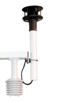
The WindSonic1-ETM is a two-dimensional ultrasonic anemometer for measuring wind speed and direction. On this version of the WindSonic1, the cable is fitted with a connector and has the ideal length for attachment to the ET107 Station. The WindSonic1-ETM includes a 1.2 ft pipe that can be used with the ET107’s crossarm U-bolt bracket.
WindSonics are manufactured by Gill Instruments Ltd.
Read MoreImages

Related Products
Technical Description
The WindSonic1 uses two pairs of orthogonally oriented transducers to sense the horizontal wind. The transducers bounce the ultrasonic signal from a hood, thus minimizing the effects of transducer shadowing and flow distortion.
Unlike mechanical anemometers, the WindSonic1 has no moving parts to be periodically replaced—minimizing routine maintenance costs.
Specifications
| Operating Humidity | < 5% to 100% RH |
| Operating Temperature | -35° to +70°C |
| Storage Temperature | -40° to +80°C |
| Input Voltage | 9 to 30 Vdc |
| Typical Current Drain | ~15 mA (continuous) |
| Measurement Frequency | 40 Hz block averaged to a 1 Hz output frequency |
| Outputs Parameters | Polar (direction and speed) or orthogonal (Ux and Uy wind) |
| Output Signal | RS-232 |
| Maximum Cable Capacitance | 2500 pF |
| Maximum Cable Length |
15.24 m (50 ft) For configurations requiring longer cable lengths, contact an application engineer at Campbell Scientific. |
| Diameter | 14.2 cm (5.6 in.) |
| Length | 16.0 cm (16.3 in.) |
| Weight | 0.5 kg (1.1 lb) |
Wind Direction |
|
| Range | 0° to 359° (no dead band) |
| Accuracy | ±3° |
| Resolution | 1° |
Wind Speed |
|
| Range | 0 to 60 m/s |
| Accuracy | ±2% (@ 12 m s-1) |
| Resolution | 0.01 m/s |
Related Documents
Product Brochures
Related FAQs
Number of FAQs related to WINDSONIC1-ETM: 2
-
Most Campbell Scientific sensors are available as an –L, which indicates a user-specified cable length. If a sensor is listed as an –LX model (where “X” is some other character), that sensor’s cable has a user-specified length, but it terminates with a specific connector for a unique system:
- An –LC model has a user-specified cable length for connection to an ET107, CS110, or retired Metdata1.
- An –LQ model has a user-specified cable length for connection to a RAWS-P weather station.
If a sensor does not have an –L or other –LX designation after the main model number, the sensor has a set cable length. The cable length is listed at the end of the Description field on the product’s Ordering tab. For example, the 034B-ET model has a description of “Met One Wind Set for ET Station, 67 inch Cable.” Products with a set cable length terminate, as a default, with pigtails.
If a cable terminates with a special connector for a unique system, the end of the model number designates which system. For example, the 034B-ET model designates the sensor as a 034B for an ET107 system.
- –ET models terminate with the connector for an ET107 weather station.
- –ETM models terminate with the connector for an ET107 weather station, but they also include a special system mounting, which is often convenient when purchasing a replacement part.
- –QD models terminate with the connector for a RAWS-F Quick Deployment Station.
- –PW models terminate with the connector for a PWENC or pre-wired system.
-
Many Campbell Scientific sensors are available with different cable termination options. These options include the following:
- The –PT (–PT w/Tinned Wires) option is the default option and does not display on the product line as the other options do. The cable terminates in pigtails that connect directly to a datalogger.
- In the –C (–C w/ET/CS110 Connector) option, the cable terminates in a connector that attaches to a CS110 Electric Field Meter or an ET-series weather station.
- In the –CWS (–CWS w/CWS900 Connector) option, the cable terminates in a connector that attaches to a CWS900-series interface. Connection to a CWS900-series interface allows the sensor to be used in a wireless sensor network.
- In the –PW (–PW w/Pre-Wire Connector) option, the cable terminates in a connector that attaches to a prewired enclosure.
- In the –RQ (–RQ w/RAWS Connector) option, the cable terminates in a connector that attaches to a RAWS-P Permanent Remote Automated Weather Station.
Note: The availability of cable termination options varies by sensor. For example, sensors may have none, two, or several options to choose from. If a desired option is not listed for a specific sensor, contact an application engineer at Campbell Scientific for assistance.
