Line of Sight: More than Meets the Eye
by Travis McKissack | Updated: 07/21/2016 | Comments: 0

When it comes to designing an RF (radio frequency) telemetry link, many people know that you need to ensure that there is an unobstructed line-of-sight (LOS) between the transmitting and receiving antennas. Unfortunately, many people don’t know that there is more to this seemingly obvious rule than meets the eye. In this introductory article, I’ll explain what exactly LOS is and the various factors that can affect your LOS communications. To help explain this, I’ll introduce a few concepts along the way that may be new to you.
What is line-of-sight propagation?
Radio signals and light waves are manifestations of electromagnetic (EM) radiation, differing chiefly in frequency. For radio transmissions, EM energy radiates from an antenna and propagates through space as a sequence of ever-expanding, spherical wavefronts. Although the energy is radiated in nearly all directions, some portion of the EM wavefront will follow the shortest, most direct path between the transmitting and
What factors can affect line-of-sight communications?
A number of factors, some of which are less obvious than others, can have a significant impact on your communication.
Reflective Obstacles
From the perspective of the receiving antenna, the direct, LOS path of propagation constitutes the bulk of the received signal, but wavefronts that have traveled an indirect path may also arrive at the receiving antenna. Physical elements, or obstacles, along the path of propagation can cause some portion of the propagating wavefront to be reflected. If the reflected wavefront arrives at the receiving antenna at the same time as the direct wavefront, the effect could be an increase or a decrease in the received signal level depending on the relative phase and amplitude of the wavefronts.
Examples of these physical elements include natural or man-made obstacles such as mountains, buildings, metallic structures, or even the surface of the intervening terrain (particularly, bodies of water).
Obstacles that Block the Direct Line-of-Sight Path
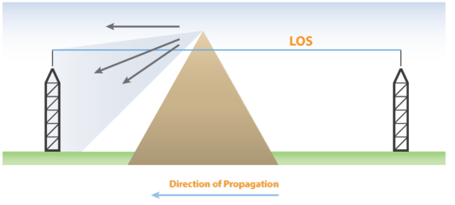
When the direct LOS path is totally obstructed, diffraction—the bending of EM wavefronts over or around an obstacle—becomes the dominant propagation mechanism for wavefronts reaching the receiving antenna. The loss, relative to the direct path, can be significant. Any signal reaching a receiving antenna located in an obstacle’s shadow is heavily affected by the shape of the obstacle and the path geometry.
- For obstacles with smooth, rounded surfaces, such as the top of a grassy hill, the signal could be totally obliterated.
- If the obstacle exhibits a sharp, knife-edge type of profile, such as with tops of buildings and some forested or rocky mountain tops, a greater portion of a propagating wavefront will be diffracted around or over the obstacle.

What is an unobstructed line-of-sight path of propagation?
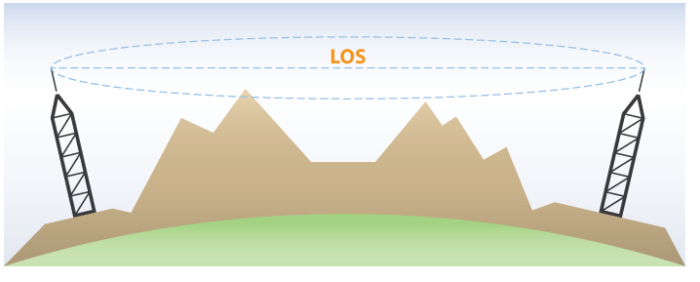
To be considered an unobstructed LOS path of propagation, a minimum volume of space normal to the direct LOS path must be kept free of obstructions. This required keep-out area is defined via the concept of Fresnel zones.
A Fresnel zone can be imagined as the area of a circle centered on and perpendicular to a given point located on the direct LOS path. The radius of the circle is related to the position of the point along the LOS path such that its maximum is at the midpoint and its minimum is at the endpoints. Thus, the area described by the Fresnel zone radius at successive points along the LOS path is an elliptical volume.

In theory, there are an infinite number of concentric Fresnel zones about a given point, but it is the first (inner-most) Fresnel zone that defines the critical keep-out area for an unobstructed LOS.
Note: Bear in mind that a Fresnel zone constitutes a three-dimensional area, so obstructions can intrude from above, below, or from the sides of the LOS path.
When obstacles intrude into the first Fresnel zone but do not block the LOS path, there is a decrease or fading of the received signal level. At the point where the obstruction becomes tangent to the LOS path, signal losses can be as much as 6 dB or more. A best practice is to maintain at least 60% of the first Fresnel zone radius free of obstructions to avoid fading of the received signal.
How much signal loss can occur because of reflection or diffraction?
In general, the following applies to a situation where an obstruction exists in the path of propagation:
- For a path of propagation where the first Fresnel zone is clear of obstructions, signal loss due to reflections or diffraction is negligible.
- For a path of propagation where more than 60% of the first Fresnel zone radius is obstructed, but the direct LOS is not obstructed, signal loss due to reflections can be up to 6 dB.
- For a path of propagation where a single knife-edge type of obstruction occludes the direct LOS, but less than 60% of the first Fresnel zone radius above the LOS, signal loss due to diffraction can be up to 14 dB.
- For a path of propagation where a single knife-edge type of obstruction occludes the direct LOS and the entire first Fresnel zone, signal loss due to diffraction can be greater than 20 dB.
More Information
From reading this introductory article, I hope you can see that the concept of LOS and the goal of an unobstructed LOS are not simple matters. For a more in-depth discussion of this topic and information on how to calculate Fresnel zone clearance and losses due to reflection and diffraction, I invite you to review the "Line of Sight Obstruction" application note.
If you have any questions about LOS, post them below.


 Travis McKissack (now retired) was a Product Test Engineer in the Product Test Group at Campbell Scientific, Inc., providing testing and second-tier support for an array of Campbell Scientific software and data communications products. He has an extensive systems engineering background in the areas of defense electronics and oceanography with an emphasis on RF systems and data telemetry.
Comments
Please log in or register to comment.